Firmware and Calibration
The Studica Hardware Manager (SHM) manages firmware updates and calibration for the NavX3.
Connecting to PC
You can connect the NavX3 to any computer supported by the SHM.
Firmware Updating
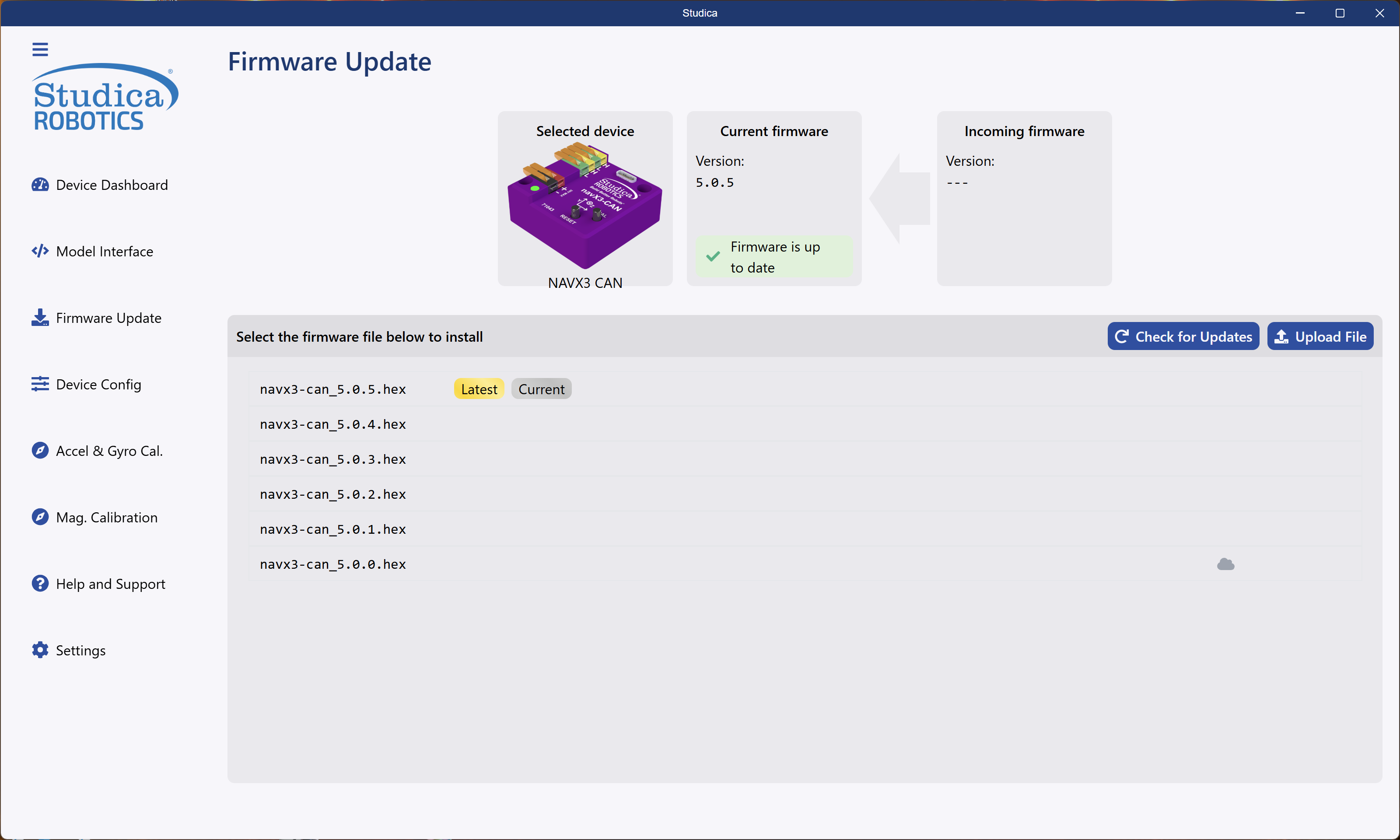
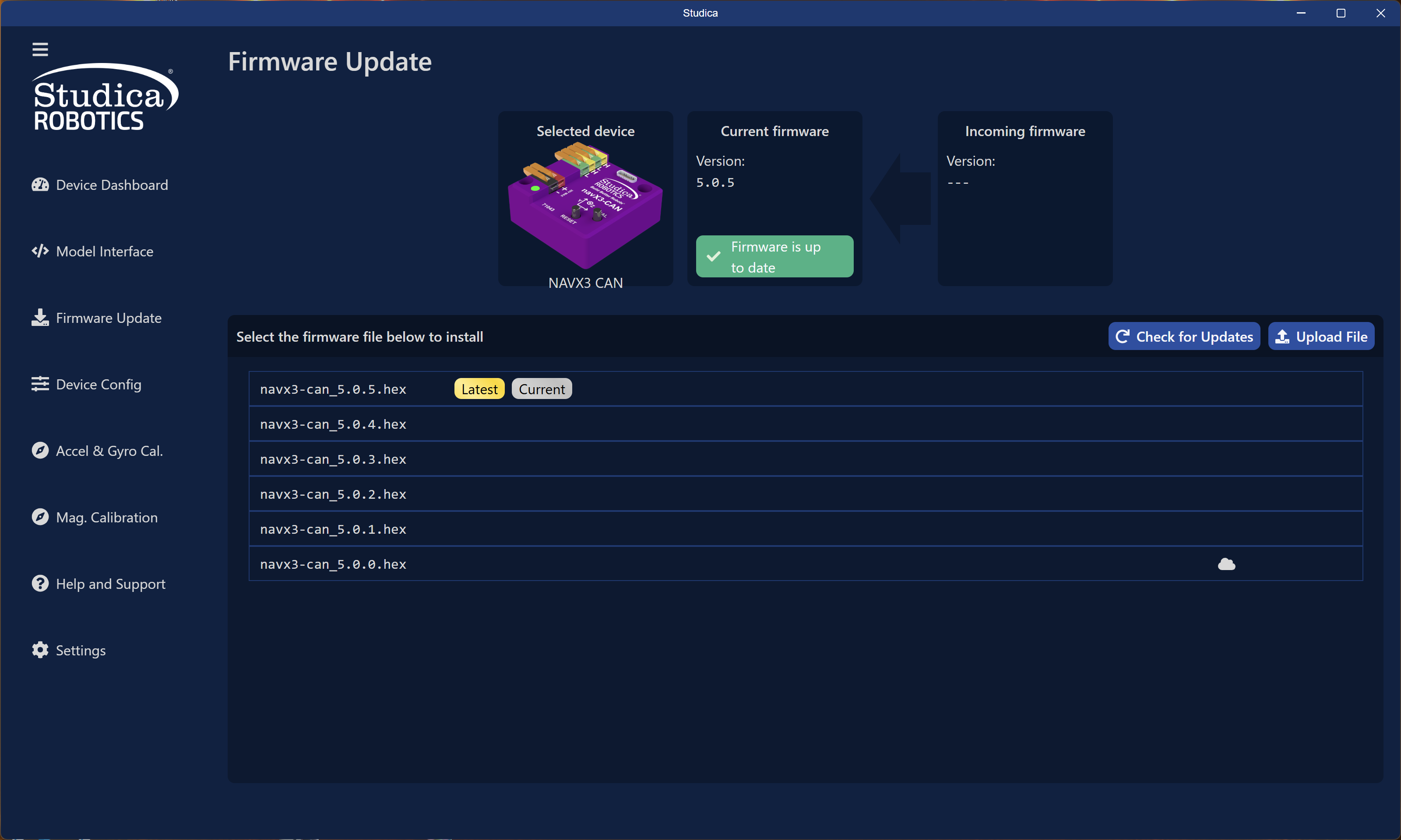
Firmware updating takes place on the firmware update tab. Download new firmware from the Studica Cloud or upload it manually using the upload button. The NavX3 does not require manual DFU booting; the software handles everything.
Steps to update firmware:
- Download, upload, or select the firmware version and click Install.
- SHM will put the device into DFU mode.
- Firmware will start uploading to the device.
- The device will automatically exit DFU mode and restart.
Config Settings
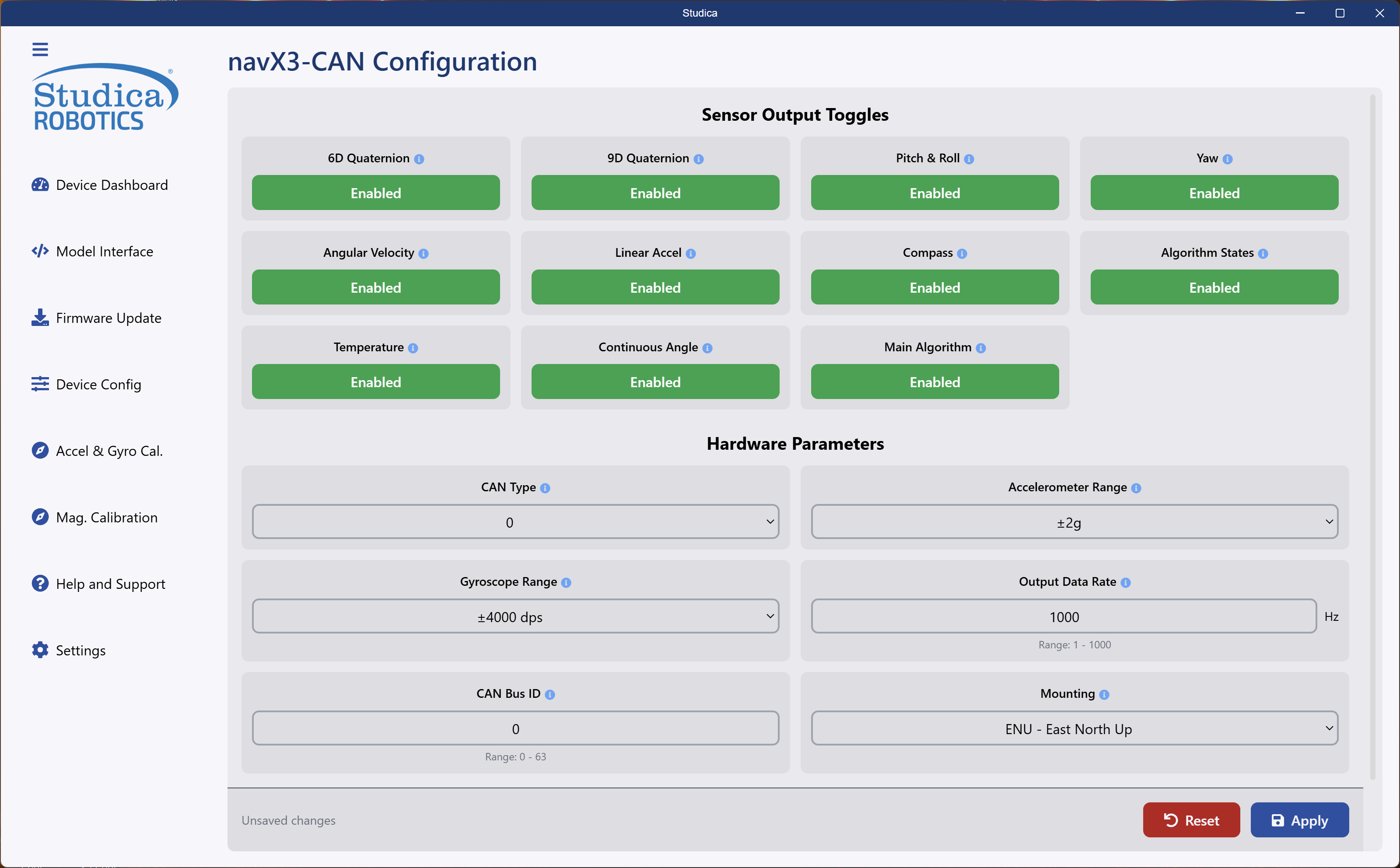
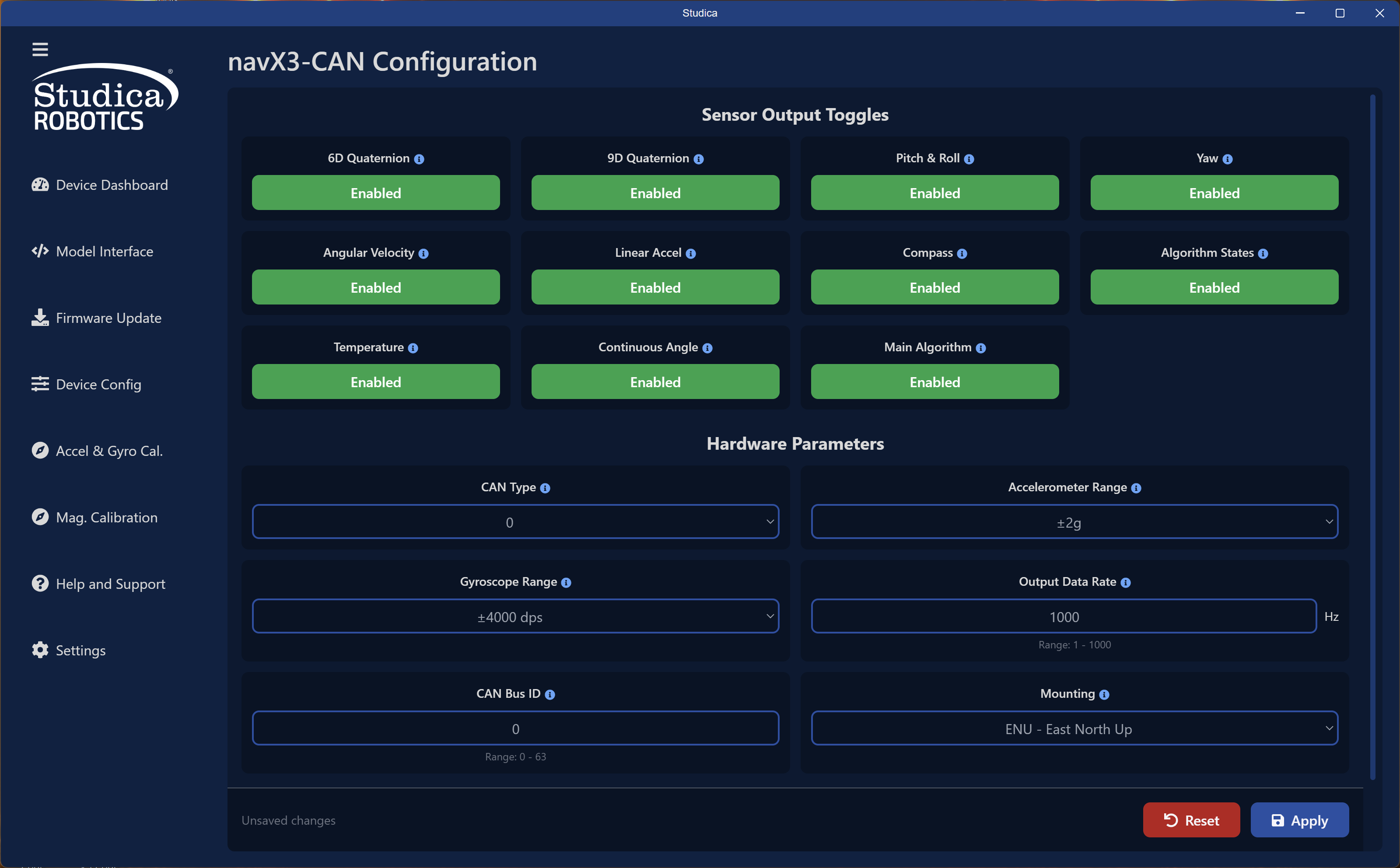
Sensor Output Toggles
To prevent CAN bus saturation, turn off unused messages. You can control these dynamically in code, but saving the configuration to EEPROM prevents the firmware from transmitting them. Each option functions as a boolean toggle.
Hardware Parameters
Hardware Parameters
CAN Type
Currently does nothing, future will control protocol ex CAN 2.0 vs CAN-FD.
Accelerometer Range
Select between the available sensor motion ranges for the NavX3 Accelerometer.
Having the lowest possible range will increase accuracy. Going lower than what your robot is doing or pulling can cause saturation.
Gyroscope Range
Select between the available sensor motion ranges for the NavX3 Gyroscope.
Having the lowest possible range will increase accuracy. Going lower than what your robot is doing or pulling can cause saturation.
Output Data Rate
The rate at which you want the sensor to send information to the user. Range is 1 - 1000 Hz.
CAN Bus ID
The ID you want your NavX3 to have. Range is 0 - 63, allowing up to 64 NavX3's on one robot!
Mounting
A way for you to show how the NavX3 is mounted. Running an Accel & Gyro calibration will override this setting.
Hitting Apply at the bottom will save the values to the EEPROM. Without hitting apply the values will not save.
Accelerometer and Gyro Calibration
Run this calibration after mounting the NavX3 on your robot with your robot on the field.
Starting Screen
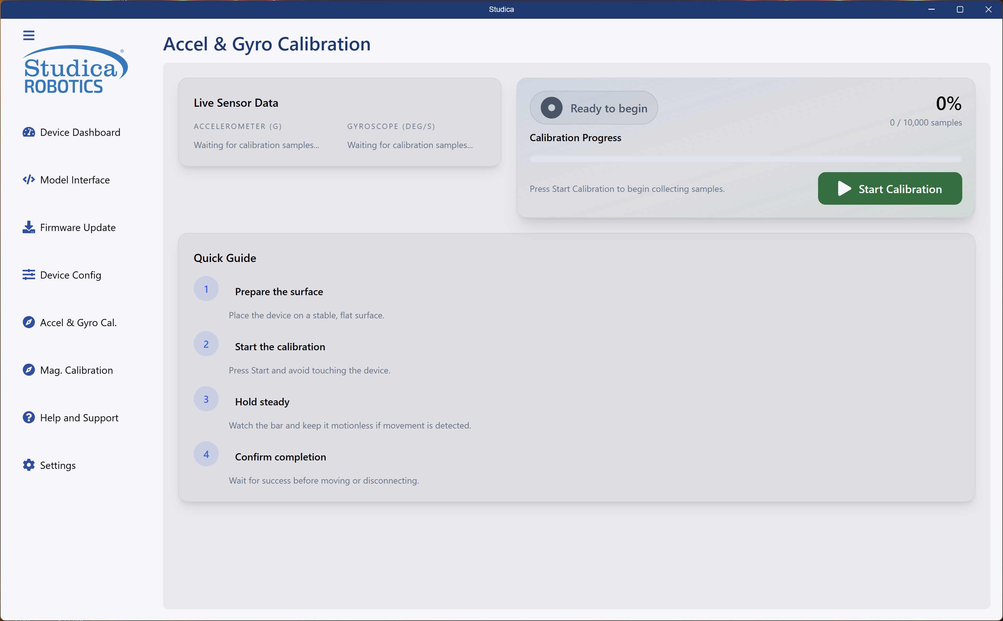
Hit Start Calibration to start the calibration process. The calibration will take 10,000 samples to calculate the correct mounting matrix for the Accelerometer and Gyroscope to work correctly.
The system detects movement and restarts the calibration. If the loop gets stuck, power cycle.
Calibration in Progress
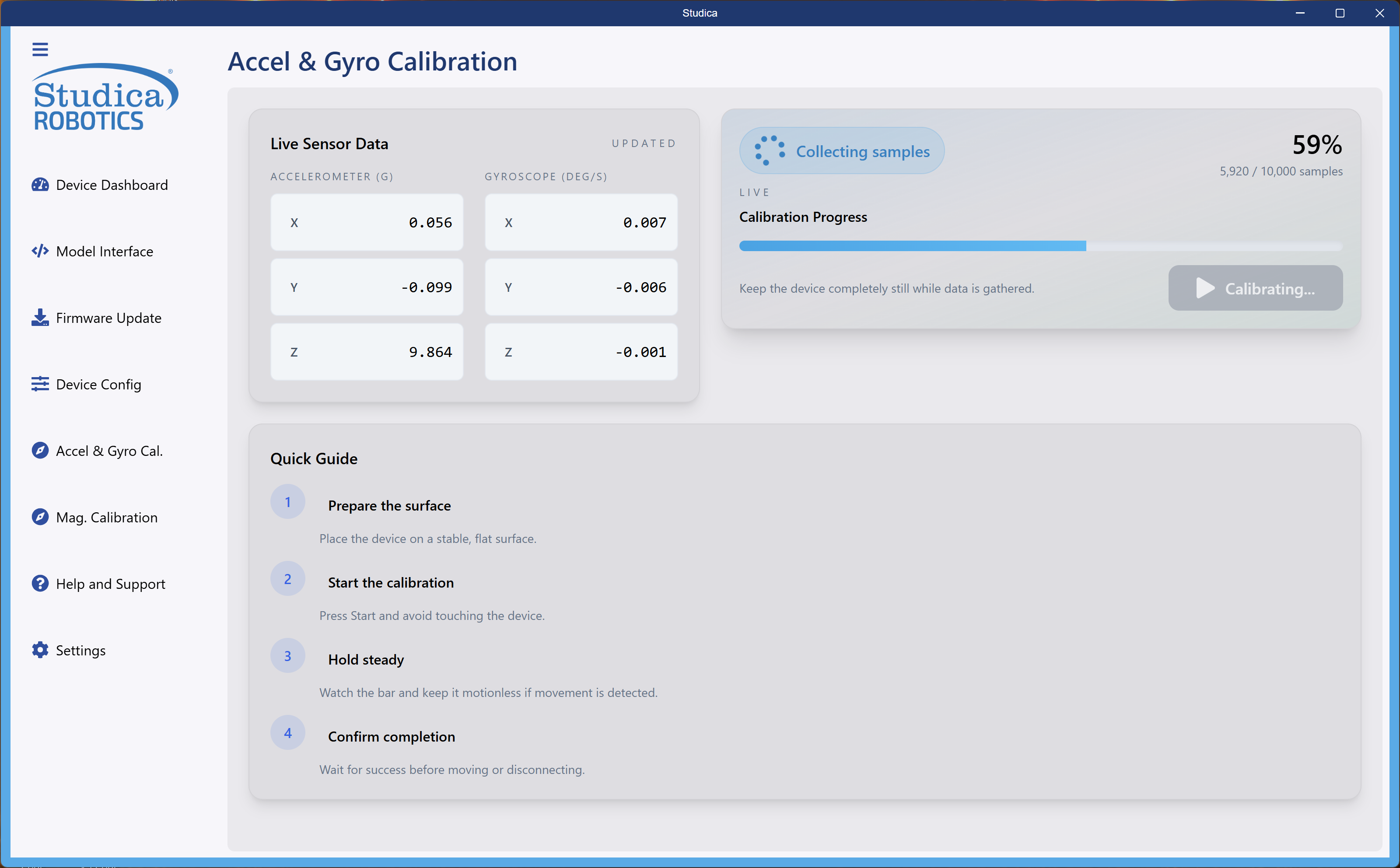
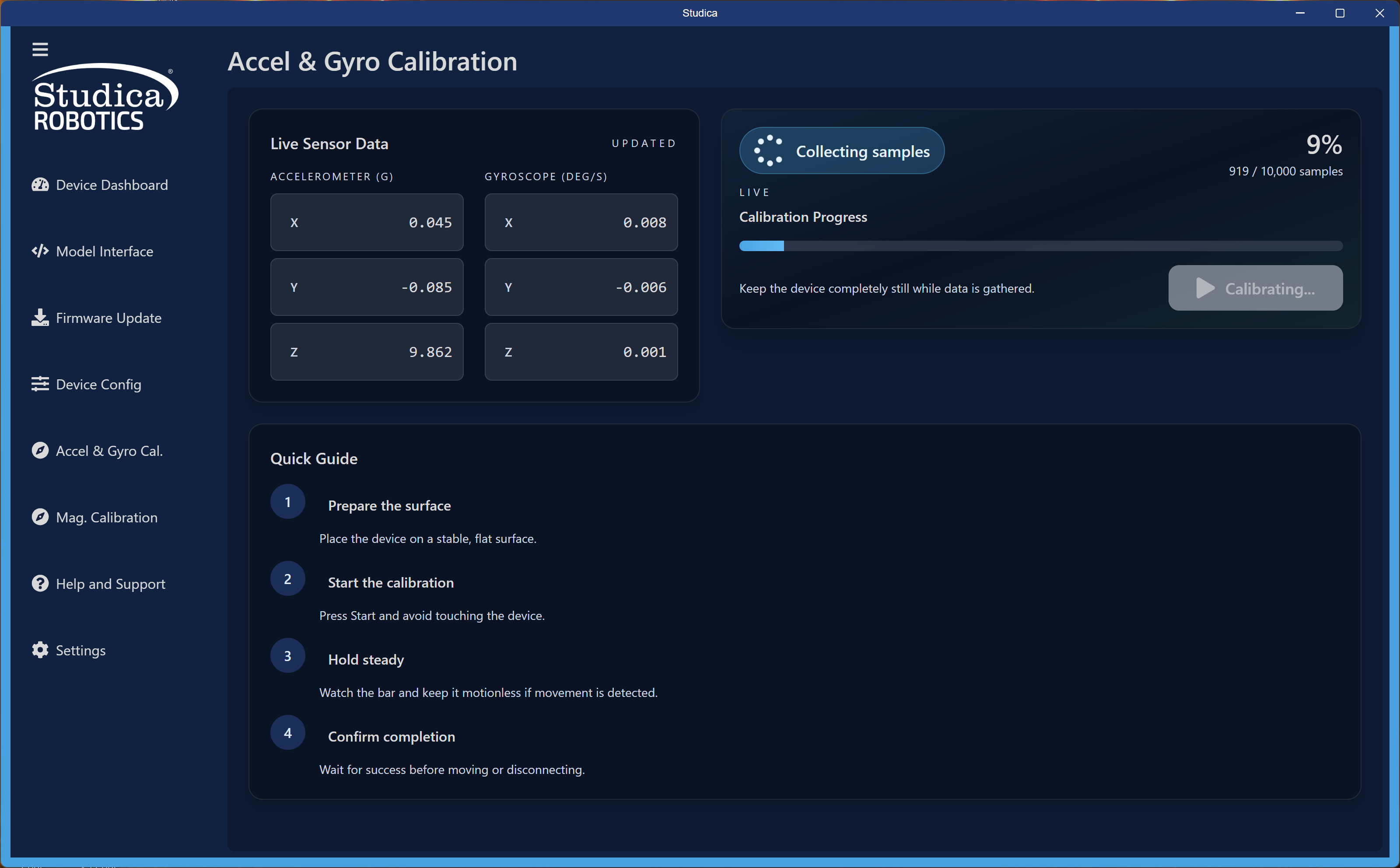
Example of the NavX3 collecting samples. View live Accelerometer and Gyroscope values during calibration.
Calibration Complete
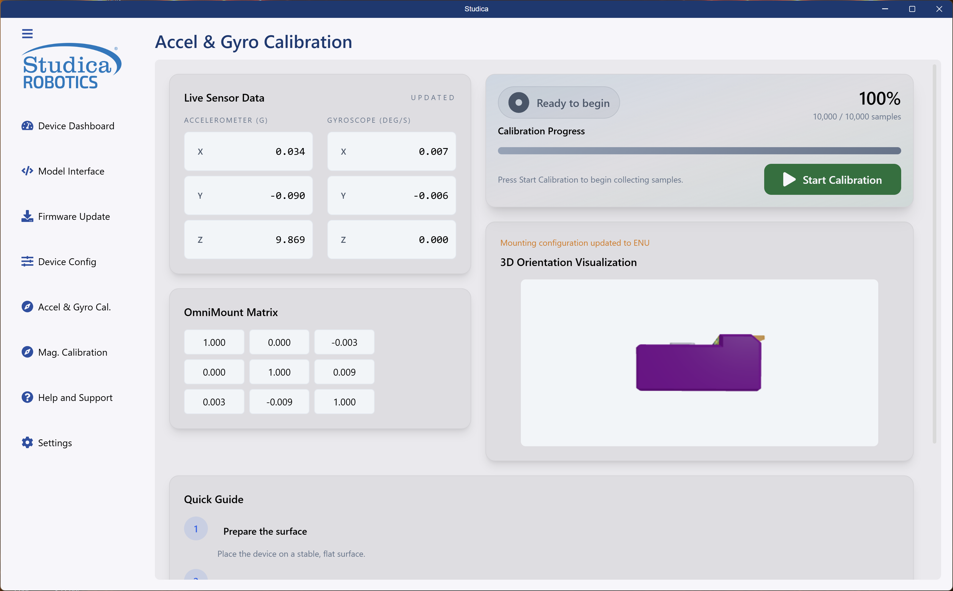
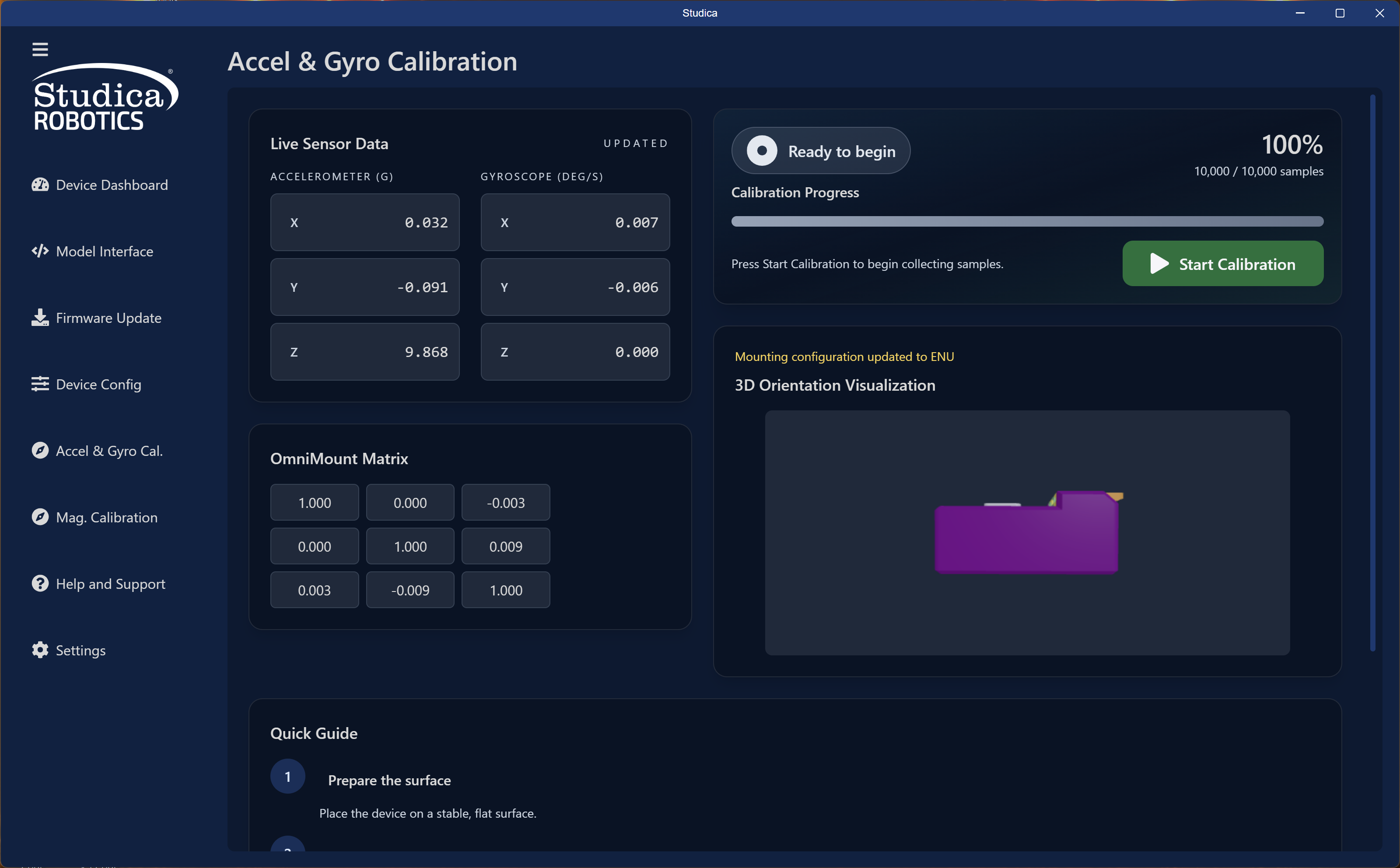
At completion of the calibration a small animation will show the orientation of the NavX3. Feel free to do some cool creative mountings! The interface displays the mounting matrix and saves it to EEPROM upon successful completion.
Magnetometer Calibration
Run this calibration before mounting the NavX3. For best results, perform it near the final mounting location with all motors energized.
Starting Screen
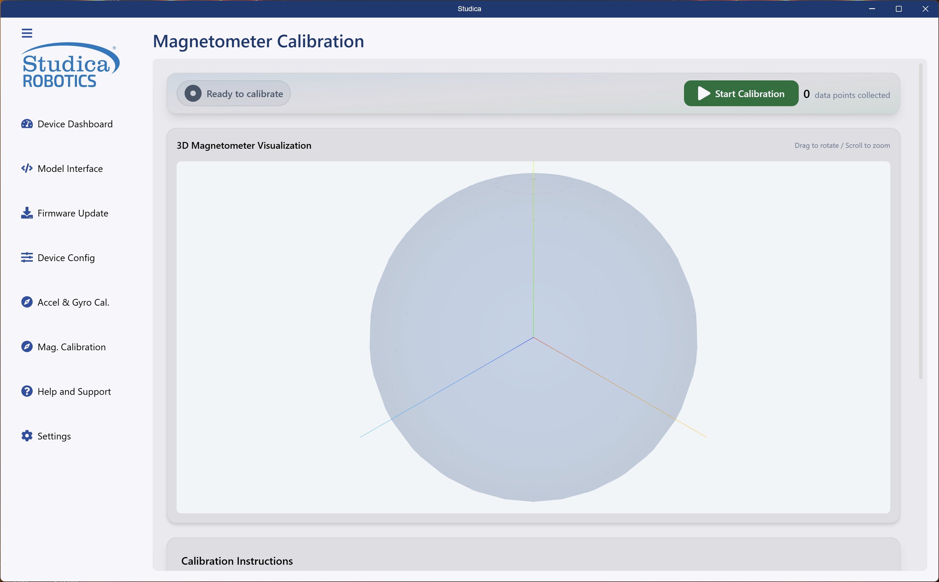
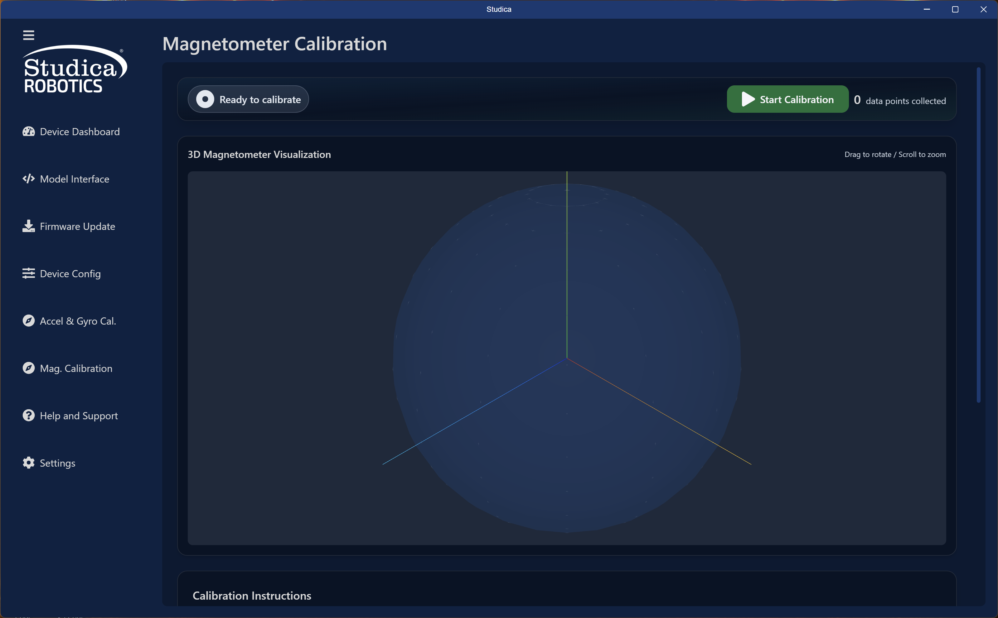
Hit Start Calibration to start the calibration process. This calibration runs until you press Stop Calibration.
Calibration in Progress
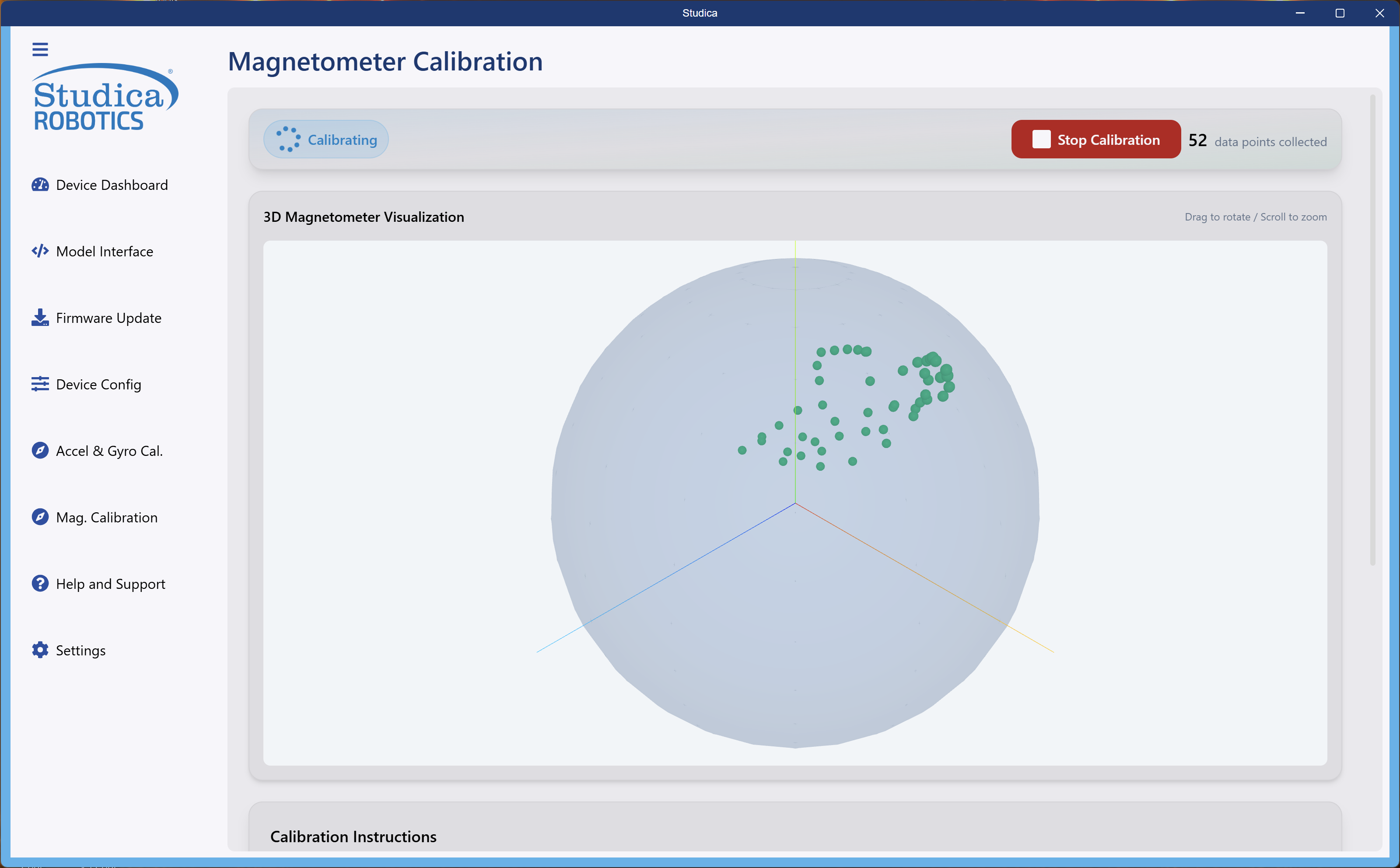
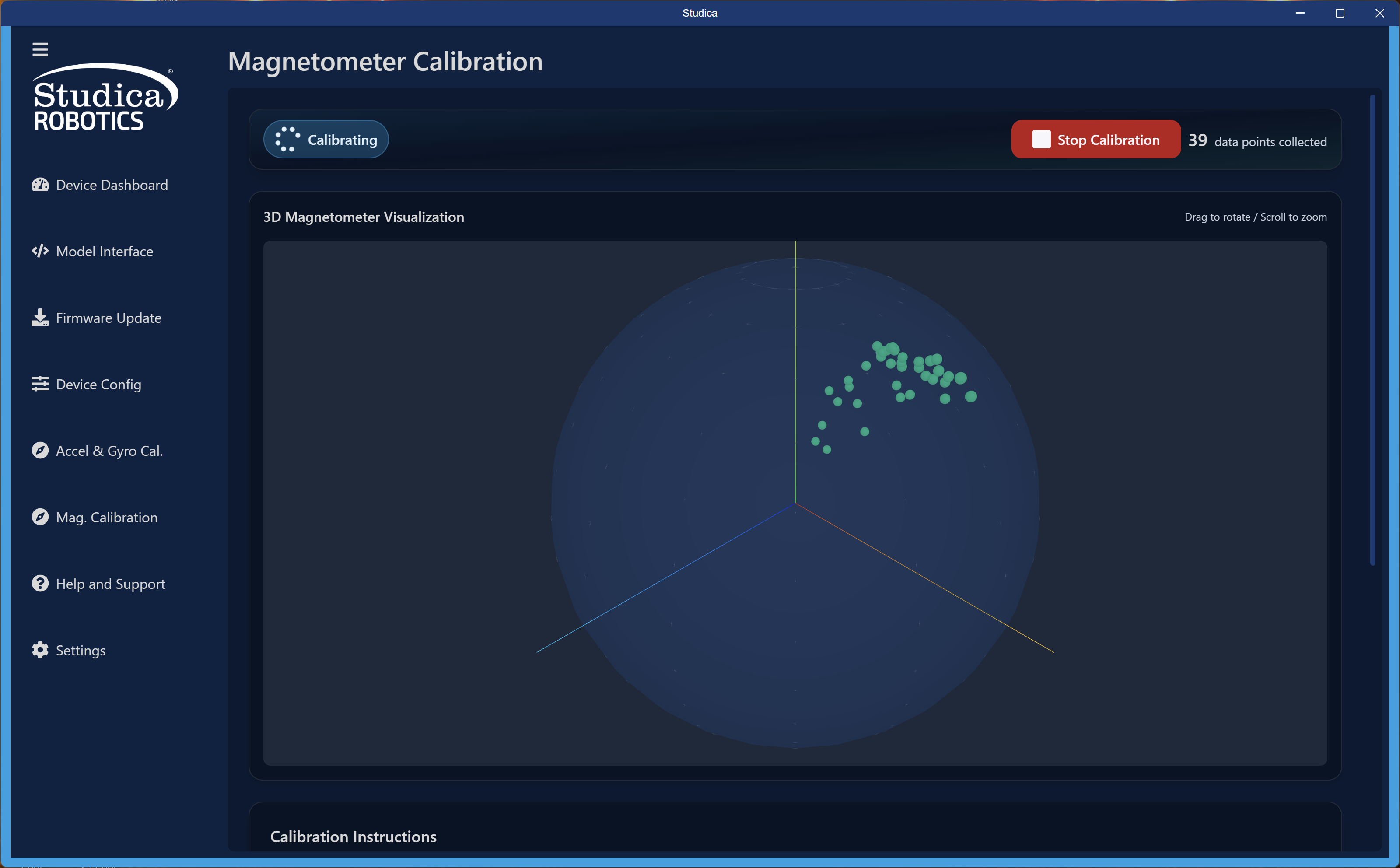
As calibration starts, dots will start appearing in the reference sphere or outside the sphere. Try to fill this area as much as possible. Ideally 800 - 1000 data points can create a successful ellipsoid model.
Moving in a figure 8 pattern will produce good results.
Calibration Complete
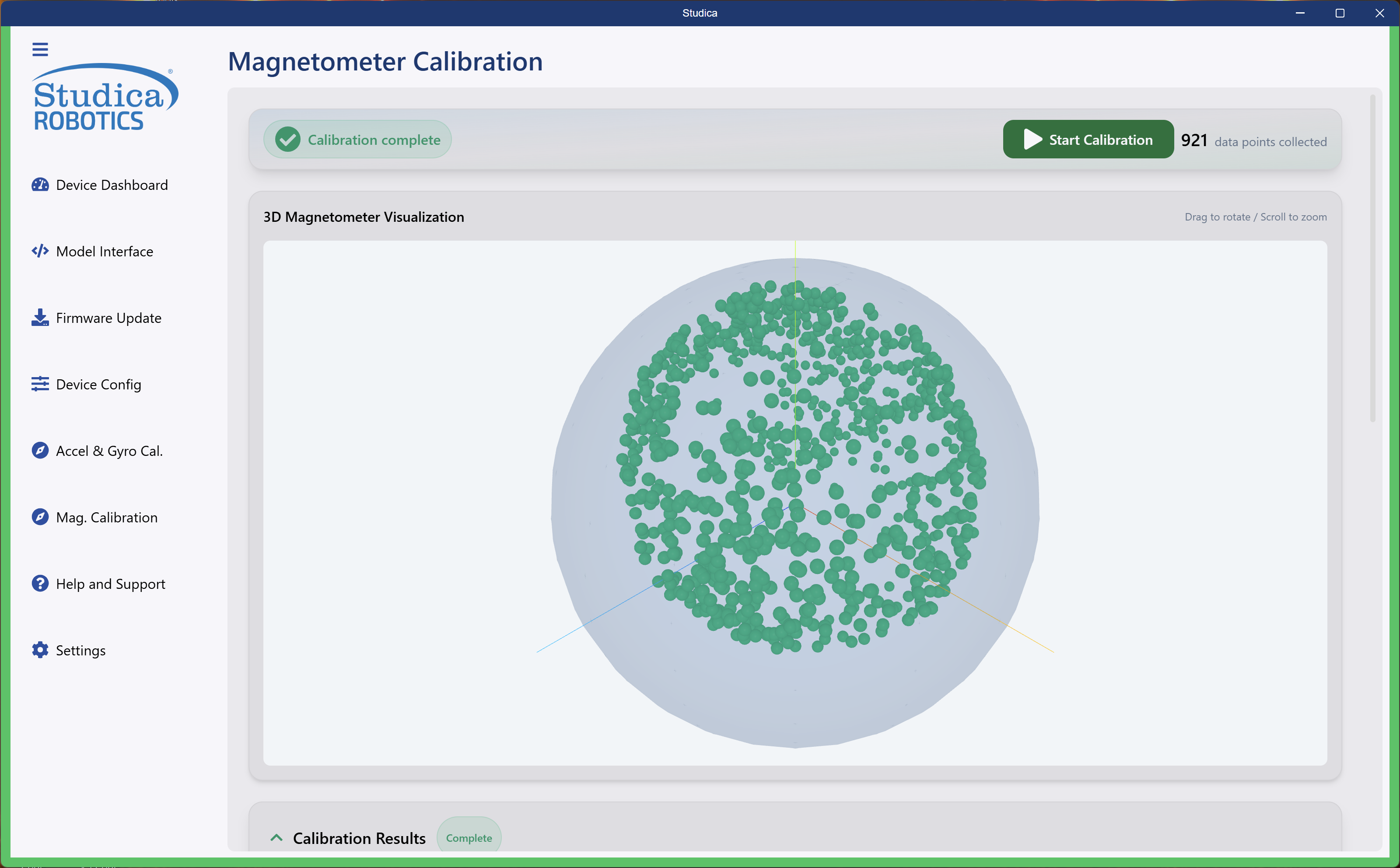
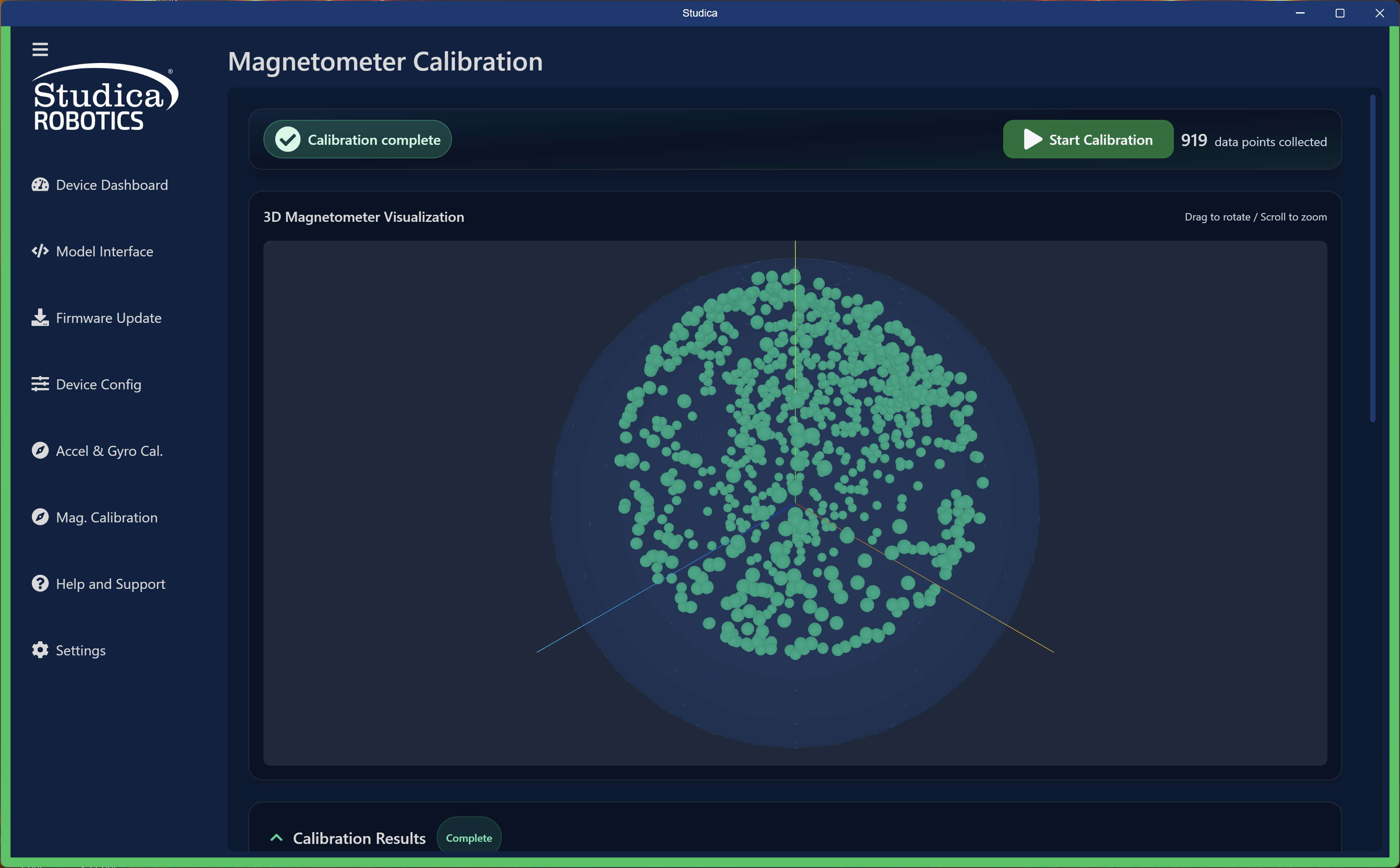
After calibration completes, review the results. The interface displays the Hard and Soft Iron values and saves them to EEPROM upon success.
The system does not save raw data points. It saves only the calculated Hard and Soft Iron constants.