Pin Out
Connector reference for the Studica Robotics Titan Motor Controller.
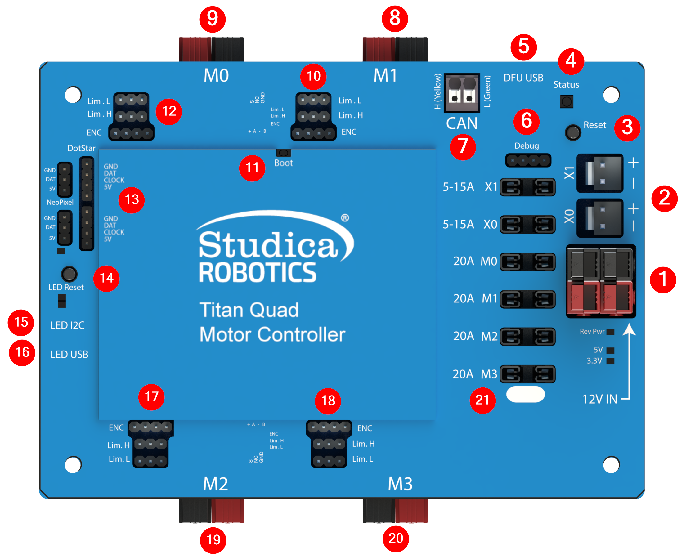
Titan connector locations and callouts. See the table below for what each numbered callout does.
| Callout | Name | What it’s for | Notes |
|---|---|---|---|
| 1 | Main Power Input | Primary power input to the Titan | Use either input; both are tied in parallel. |
| 2 | External Outputs | Pass-through outputs at the same voltage as the main input | Typically used to power external devices that accept the same supply voltage. |
| 3 | Reset button | Resets the Titan | — |
| 4 | Status LED | Controller status indication | See status LED page |
| 5 | USB (Titan) | Programming / firmware update / diagnostics | USB connection to the main controller. |
| 6 | Debug header | Internal use only | Not intended for user wiring. |
| 7 | CAN 2.0B header | CAN communication | Has terminator resistor soldered on |
| 8 | Motor 1 output | Motor channel 1 power output | — |
| 9 | Motor 0 output | Motor channel 0 power output | — |
| 10 | Motor 1 encoder/limit | Encoder + limit switch for motor 1 | — |
| 11 | Boot button | Bootloader / recovery mode access | Used for firmware recovery (see firmware update page). |
| 12 | Motor 0 encoder/limit | Encoder + limit switch for motor 0 | — |
| 13 | RGB LED ports | RGB LED outputs | Driven by the onboard LED controller. |
| 14 | LED controller reset | Resets the LED controller | — |
| 15 | I2C port (LED controller) | I2C communication for LED controller | Voltage level is 5V |
| 16 | LED controller USB | Programming the LED controller | Separate from the Titan USB port. |
| 17 | Motor 2 encoder/limit | Encoder + limit switch for motor 2 | — |
| 18 | Motor 3 encoder/limit | Encoder + limit switch for motor 3 | — |
| 19 | Motor 2 output | Motor channel 2 power output | — |
| 20 | Motor 3 output | Motor channel 3 power output | — |
| 21 | Fuse holders | Channel / system fuse locations | Use only the specified fuse type/rating. |